Reolink RLN12W Stability Threshold: When a WiFi NVR Starts to Drift
ANALYSIS FRAMEWORK
Intent Lock
If your RLN12W system begins stable but later develops delay, reconnects, or intermittent camera loss,
this is rarely configuration error.
It is usually a load threshold that becomes visible only after the system accumulates enough simultaneous streams.
This is a single-threshold system.
When stream density and Wi-Fi airtime contention accumulate over time, stability begins to drift — even if no settings change.
What Stability Drift Means
Stability drift is the moment when a recorder continues functioning but no longer behaves predictably.
In practice this is when the system stops feeling instant.
The live view still works.
Recording still happens.
But response becomes slower, reconnects appear, and the system begins operating closer to its internal limits.
A security recorder rarely fails randomly.
It fails when load reveals the system’s real limit.
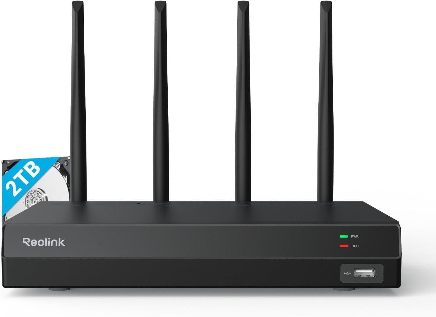
The Hardware Commitments
The RLN12W is built around a specific set of physical constraints.
These constraints define the performance envelope of the system.
| Hardware Element | Operational Meaning |
|---|---|
| 16 recording channels | The recorder can aggregate up to 16 simultaneous camera streams |
| Maximum camera resolution: 16MP | Higher resolution streams increase bitrate and decoding load |
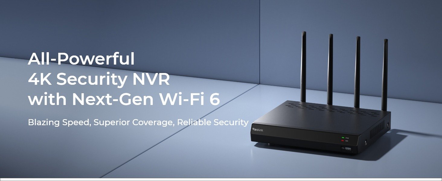
| Dual-band WiFi 6 (2.4 / 5 GHz) with WPA3 | Camera transport occurs over shared RF airtime |
| Built-in 2TB HDD | Continuous recording begins consuming retention capacity immediately |
| Storage expansion up to 8TB | Retention window depends on camera count and resolution |
| No PoE ports | Power delivery occurs outside the recorder |
| HDMI / VGA output + Ethernet initialization | Initial configuration expects a wired LAN handshake |
These specifications create a predictable operating environment.
They also define where stability limits eventually appear.
Observable Signals Before Collapse
When a WiFi NVR approaches its threshold, the system rarely fails instantly.
Instead it exposes small, repeatable signals.
The three signals that appear first are:
- Latency Spike
Live view that was previously near-real-time begins showing several seconds of delay. - Reconnect Frequency
Cameras briefly disconnect and reconnect even though signal strength appears normal. - Throughput Drop
Playback becomes slower when multiple cameras detect motion simultaneously.
When these three signals begin clustering together, the system is approaching its stability boundary.
The Hidden Variable: Airtime Competition
Many users assume WiFi 6 eliminates wireless congestion.
In reality, WiFi still depends on shared airtime.
Each camera competes for transmission time on the radio channel.
As more cameras stream simultaneously, the available airtime per device decreases.
The result is not instant failure.
Instead the system gradually develops latency drift and reconnect clustering.
WiFi range is not the same thing as multi-stream stability.
Threshold Bands in Real Deployments
A useful way to understand system behavior is to observe how load increases across camera density.
Typical patterns follow these operational bands.
| Camera Count | Typical Behavior |
|---|---|
| 4 cameras | Baseline stability. Minimal contention. |
| 8 cameras | Near-threshold. Occasional latency spikes may appear. |
| 12 cameras | RF airtime pressure increases noticeably. |
| 16 cameras | Drift risk increases under heavy motion events. |
These numbers are not marketing limits.
They are practical load bands where WiFi-based recording systems begin revealing their internal constraints.
Failure Signature
Every system has a recognizable collapse pattern.
The RLN12W failure signature typically appears as:
- Trigger
Camera count or motion activity increases until the recorder behaves like a fully loaded aggregation system. - Symptom
Live view delay grows from near-instant to several seconds. - Repeat Interval
Cameras begin reconnecting in clusters during peak wireless activity. - Drift Marker
Reconnect cycles begin repeating every few minutes rather than appearing as isolated events.
What makes the pattern confusing is that the system still records successfully.
The instability appears mostly in live viewing and reconnection behavior.
Deployment Scenarios
- Low Load Deployment
Small homes with limited camera count operate comfortably below the threshold.
The recorder remains responsive and stable. - Medium Load Deployment
Typical households with several cameras begin approaching the threshold during peak network activity.
Latency spikes may appear occasionally. - High Load Deployment
Large camera counts or dense WiFi environments push the recorder closer to its limits.
This is where reconnect clustering and drift markers become visible.
Decision Threshold
If your environment approaches the upper camera density bands or operates in a crowded wireless spectrum, the purchase decision becomes structural rather than preference-based.
Memory Imprint
A WiFi security system rarely fails randomly.
It fails when load reveals the system’s real limit.
Transparency Note:
This analysis is not based on quick personal impressions.
It is derived from documented system behavior, verified user patterns, and the physical constraints of storage capacity.
The goal is to translate complex technical behavior into a realistic performance model that helps you make a clear decision

One Comment